image

Clemmer Group

Development of New Ion Mobility Instrumentation


  1. Introduction
  2. Multidimensional Separation Methods
  3. Drift Tube Designs
  4. Instrumentation
  5. Relevant Publications


Introduction


The Clemmer Group has, and continues, to devote a major effort toward the development of new instrumentation with two primary goals in mind:

Our instruments are constructed in a modular fashion such that many components are interchangeable. Pictures and more information on some of our original custom designs can be found below.


Multidimensional Separations Methods


Biomolecular mixtures containing more than a few components become increasingly more difficult to analyze as the number of components increases. The presence of different charge states (in the case of electrosprayed ions), sequence isomers, and other species having overlapping mass spectral peaks makes complete assignment of components impossible by mass spectrometry alone.

The timescale of ion mobility (milliseconds) provides unique opportunities for multidimensional separations. Nesting ion mobility separation between condensed phase (seconds-to-minute timescales) separations and time-of-flight mass spectrometry (microsecond timescales) is particularly desirable because of the different modes of separation involved in these methods.

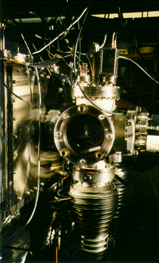
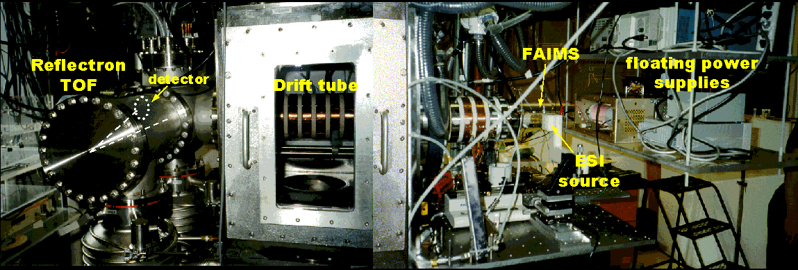
Current projects in this area include interfacing HPLC and CE separations with our existing ion mobility/TOF apparatus and investigating the capabilities of a FAIMS (field asymmetric waveform ion mobility spectrometry)/ion mobility/TOF arrangement (originally in collaboration with Guevremont and coworkers). A picture of the FAIMS/ion mobility/TOF instrument is shown below.
image


Drift Tube Designs


Injected-Ion Drift Tube

image
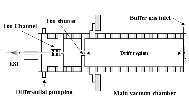
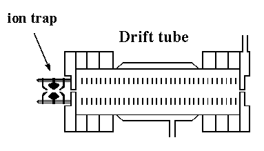
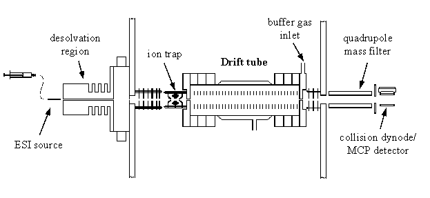
Figure 1: A schematic of the injected-ion drift tube interfaced with an ion trap.

image
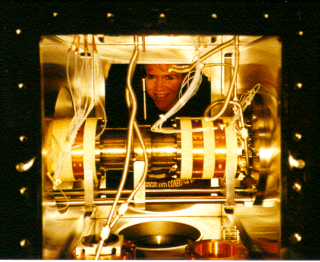
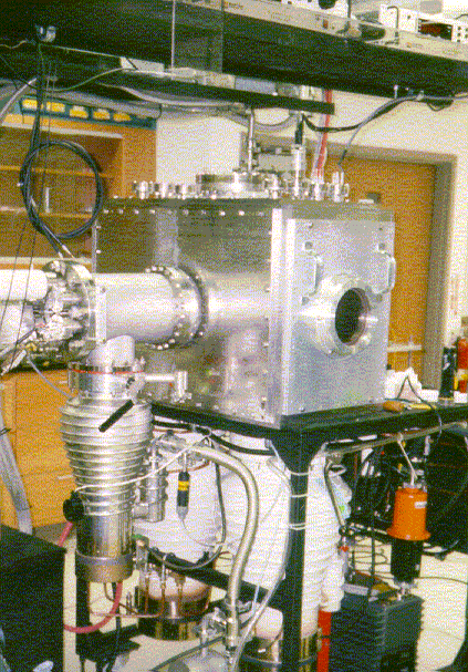
Figure 2: The injected ion drift tube is illuminated in the main vacuum chamber of the time-of-flight instrument.


High-Pressure High Resolution Drift Tube


image
Figure 3: A schematic of the high-pressure high-resolution drift tube.

image
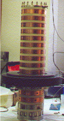
Figure 4: A picture of the free-standing drift tube.

The main advantage of this design over the injected-ion drift tube is the increase in resolving power that is attained. The resolving power of the drift tube is based on the following expression, where we can calculate resolving power from the drift time (tD) of the peak, and the width of the peak in drift space (Δt). The remaining variables are the length of the drift region (L), the strength of the applied electric field (E), the charge on the ion (ze), Boltzmann's constant (kb), and temperature (T).


image

Thus, the resolving power can be increased by a factor equal to the square root of the increase in the electric field strength. At the low pressures (1–5 torr) used in the injected-ion drift tube, high electric field strengths cannot be achieved, due to the breakdown potential of the buffer gas. However, at higher buffer gas pressures, the field strength (and thus resolving power) can be increased. Another advantage of the high pressure drift tube is that ions are not injected; thus, the ions are analyzed in a much gentler manner, allowing conformations formed in the source to be preserved.
image
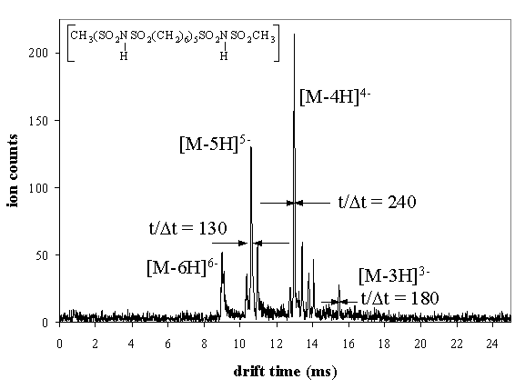
Figure 5: An example drift time distribution recorded for a small organic hexamer using this drift tube design.


Instruments


Quadrupole-Based Instrument (Selected Ions)


image
Figure 6: The quadrupole-based instrument is configured with the injected-ion drift tube.

image
Figure 7: The drift tube is housed in the main vacuum chamber, which is evacuated by two diffusion pumps. Shown at the back is the detector chamber, which contains the quadrupole mass filter and collision dynode/microchannel plate detector. An electrospray source (not visible from this angle) is used to introduce ions into the instrument.


Ion Mobility/Time-of-Flight Instrument (Mixture of Ions)


image
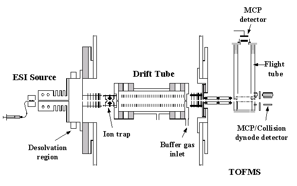
Figure 8: The ion mobility/time-of-flight instrument offers a tremendous advantage over the quadrupole system. Because flight times in the time-of-flight mass spectrometer are much shorter than drift times in the drift tube, many flight time distributions can be recorded with respect to each drift time window. The resulting three-dimensional spectrum of drift times, flight times, and intensity is called a nested drift (flight) time distribution.

image       image
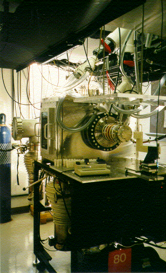
Figure 9: Pictures of the IMS–TOFMS instrument. The left picture shows the front of the instrument, where ions are injected into the drift tube, and the picture on the right shows the back of the instrument, where mass analysis is performed inside the time-of-flight (TOF) mass spectrometer.


Selected References


  1. Henderson, S. C.; Valentine, S. J.; Counterman, A. E.; Clemmer, D. E. ESI/Ion Trap/Ion Mobility/Time-of-Flight Mass Spectrometry for Rapid and Sensitive Analysis of Biomolecular Mixtures, Anal. Chem. 1999, 71, 291–301.
  2. Hoaglund, C. S.; Valentine, S. J.; Clemmer, D. E. An Ion Trap Interface for ESI-Ion Mobility Experiments, Anal. Chem. 1997, 69, 4156–4161.
  3. Liu, Y.; Valentine, S. J.; Counterman, A. E.; Hoaglund, C. S.; Clemmer, D. E. Injected-ion Mobility Analysis of Biomolecules, Anal. Chem. 1997, 69, 728A.
  4. Valentine, S. J.; Clemmer, D. E. H/D Exchange Levels of Shape-Resolved Cytochrome c Conformers in the Gas Phase, J. Am. Chem. Soc., 1997, 119, 3558–3566.
  5. Srebalus, C. A.; Li, J.; Marshall, W. S.; Clemmer, D. E. Determining Synthetic Failures in Combinatorial Libraries by Hybrid Gas-Phase Separation Methods, J. Am. Soc. Mass Spectrom. 2000, 11, 352–355.
  6. Li, J.; Taraszka, J. A.; Counterman, A. E.; Clemmer, D. E. Influence of solvent composition and capillary temperature on the conformations of electrosprayed ions: unfolding of compact ubiquitin conformers from pseudonative and denatured solutions, Int. J. Mass. Spectrom. 1999, 185–187, 37–47.
  7. Counterman, A. E.; Valentine, S. J.; Srebalus, C. A.; Henderson, S. C.; Hoaglund, C. S.; Clemmer, D. E. High-Order Structure and Dissociation of Gaseous Peptide Aggregates that are Hidden in Mass Spectra, J. Am. Soc. Mass Spectrom. 1998, 9, 743–759.
  8. Clemmer, D. E.; Jarrold, M. F. Ion Mobility Measurements and their Applications to Clusters and Biomolecules, J. Mass Spectrom. 1997, 32, 577–592.
  9. Hoaglund, C. S.; Valentine, S. J.; Sporleder, C. R.; Reilly, J. P.; Clemmer, D. E. Three-Dimensional Ion Mobility/TOFMS Analysis of Electrosprayed Biomolecules, Anal. Chem. 1998, 70, 2236–2242.